- 您现在的位置:买卖IC网 > Sheet目录492 > NTP65N02RG (ON Semiconductor)MOSFET N-CH 25V 7.6A TO220AB
�� �
�
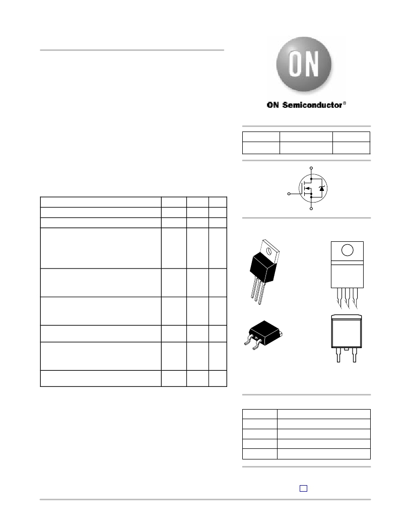
�NTB65N02R,� NTP65N02R�
�Power� MOSFET�
�65� A,� 24� V� N?Channel�
�TO?220,� D� 2� PAK�
�Features�
�?� Planar� HD3e� Process� for� Fast� Switching� Performance�
�?� Low� R� DSon� to� Minimize� Conduction� Loss�
�?� Low� C� iss� to� Minimize� Driver� Loss�
�?� Low� Gate� Charge�
�?� Pb?Free� Packages� are� Available*�
�MAXIMUM� RATINGS� (T� J� =� 25� °� C� Unless� otherwise� specified)�
�V� (BR)DSS�
�24� V�
�http://onsemi.com�
�R� DS(on)� TYP�
�8.4� m� W� @� 10� V�
�D�
�G�
�I� D� MAX�
�65� A�
�Parameter�
�Symbol�
�Value�
�Unit�
�Drain?to?Source� Voltage�
�Gate?to?Source� Voltage� ?� Continuous�
�Thermal� Resistance� ?� Junction?to?Case�
�Total� Power� Dissipation� @� T� C� =� 25� °� C�
�V� DSS�
�V� GS�
�R� q� JC�
�P� D�
�25�
�±� 20�
�2.0�
�62.5�
�V� dc�
�V� dc�
�°� C/W�
�W�
�S�
�MARKING�
�DIAGRAMS�
�Drain� Current� ?�
�Continuous� @� T� C� =� 25� °� C,� Chip�
�Continuous� @� T� C� =25� °� C,� Limited� by� Package�
�Single� Pulse� (t� p� =� 10� m� s)�
�I� D�
�I� D�
�I� DM�
�65�
�58�
�160�
�A�
�A�
�A�
�4�
�TO?220AB�
�Thermal� Resistance� ?�
�Junction?to?Ambient� (Note� 1)�
�Total� Power� Dissipation� @� T� A� =� 25� °� C�
�Drain� Current� ?� Continuous� @� T� A� =� 25� °� C�
�R� q� JA�
�P� D�
�I� D�
�67�
�1.86�
�10�
�°� C/W�
�W�
�A�
�CASE� 221A�
�STYLE� 5�
�P65N02RG�
�AYWW�
�Thermal� Resistance� ?�
�Junction?to?Ambient� (Note� 2)�
�Total� Power� Dissipation� @� T� A� =� 25� °� C�
�Drain� Current� ?� Continuous� @� T� A� =� 25� °� C�
�R� q� JA�
�P� D�
�I� D�
�120�
�1.04�
�7.6�
�°� C/W�
�W�
�A�
�1�
�2�
�3�
�Operating� and� Storage� Temperature� Range�
�Single� Pulse� Drain?to?Source� Avalanche�
�Energy� ?� Starting� T� J� =� 25� °� C�
�T� J� and�
�T� stg�
�E� AS�
�?55� to�
�150�
�60�
�°� C�
�mJ�
�2�
�1� 3�
�4�
�D� 2� PAK�
�CASE� 418AA�
�STYLE� 2�
�65N02RG�
�AYWW�
�(V� DD� =� 50� V� dc� ,� V� GS� =� 10� V� dc� ,� I� L� =� 11� A� pk� ,�
�L� =� 1� mH,� R� G� =� 25� W� )�
�65N02R� =� Specific� Device� Code�
�A� =� Assembly� Location�
�Maximum� Lead� Temperature� for� Soldering�
�Purposes,� 1/8� ″� from� Case� for� 10� Seconds�
�T� L�
�260�
�°� C�
�Y� =� Year�
�WW� =� Work� Week�
�G� =� Pb?Free� Package�
�Maximum� ratings� are� those� values� beyond� which� device� damage� can� occur.�
�Maximum� ratings� applied� to� the� device� are� individual� stress� limit� values� (not�
�normal� operating� conditions)� and� are� not� valid� simultaneously.� If� these� limits� are�
�exceeded,� device� functional� operation� is� not� implied,� damage� may� occur� and�
�PIN� ASSIGNMENT�
�reliability� may� be� affected.�
�1.� When� surface� mounted� to� an� FR4� board� using� 1� in.� pad� size,� (Cu� Area� 1.127� in� 2� ).�
�2.� When� surface� mounted� to� an� FR4� board� using� minimum� recommended� pad�
�size,� (Cu� Area� 0.412� in� 2� ).�
�PIN�
�1�
�2�
�FUNCTION�
�Gate�
�Drain�
�*For� additional� information� on� our� Pb?Free� strategy� and� soldering� details,� please�
�3�
�4�
�Source�
�Drain�
�ORDERING� INFORMATION�
�download� the� ON� Semiconductor� Soldering� and� Mounting� Techniques�
�Reference� Manual,� SOLDERRM/D.�
�See� detailed� ordering� and� shipping� information� in� the� package�
�dimensions� section� on� page� 5� of� this� data� sheet.�
�?� Semiconductor� Components� Industries,� LLC,� 2005�
�May,� 2005� ?� Rev.� 6�
�1�
�Publication� Order� Number:�
�NTB65N02R/D�
�发布紧急采购,3分钟左右您将得到回复。
相关PDF资料
NTP75N03-006
MOSFET N-CH 30V 75A TO220AB
NTP75N03L09G
MOSFET N-CH 30V 75A TO220AB
NTP75N03RG
MOSFET N-CH 25V 9.7A TO220AB
NTP75N06G
MOSFET N-CH 60V 75A TO220AB
NTP75N06L
MOSFET N-CH 60V 75A TO-220AB
NTP75N06
MOSFET N-CH 60V 75A TO220AB
NTP90N02G
MOSFET N-CH 24V 90A TO220AB
NTQD6866R2G
MOSFET 2N-CH 20V 4.7A 8TSSOP
相关代理商/技术参数
NTP685M10TRA(300)F
制造商:NIC Components Corp 功能描述:- Tape and Reel
NTP686M10TRC(100)F
制造商:NIC Components Corp 功能描述:- Tape and Reel
NTP686M10TRD(100)F
制造商:NIC Components Corp 功能描述:Cap Tant Solid 68uF 10V D CASE 20% (7.3 X 4.3 X 2.8mm) SMD 7343 0.1 Ohm 105°C T/R 制造商:NIC Components Corp 功能描述:CAP 68UF 10VDC 20% 7.3 X 4.3 X 2.8MM SMD 7343 1% - Tape and Reel 制造商:NIC Components Corp 功能描述:NTP tantalum capacitor SMT 10V 68uF 制造商:NIC Components 功能描述:Cap Tant Solid 68uF 10V D CASE 20% (7.3 X 4.3 X 2.8mm) SMD 7343 0.1 Ohm 105 制造商:NIC Components 功能描述:Cap Tant Solid 68uF 10V D CASE 20% (7.3 X 4.3 X 2.8mm) SMD 7343 0.1 Ohm 105°C T/R
NTP686M10TRV(60)F
制造商:NIC Components Corp 功能描述:- Tape and Reel
NTP686M4TRA(180)F
制造商:NIC Components Corp 功能描述:Cap Tant Solid 68uF 4V A CASE 20% (3.2 X 1.6 X 1.6mm) SMD 3216-18 0.18 Ohm 105C T/R
NTP686M4TRC(100)F
制造商:NIC Components Corp 功能描述:- Tape and Reel 制造商:NIC Components Corp 功能描述:NTP Series 68 uF 20 % 4 V Surface Mount Polymer-Tantalum Chip Capacitor
NTP686M6.3TRB(70)F
制造商:NIC Components Corp 功能描述:- Tape and Reel
NTP687M4TRD(15)F
制造商:NIC Components Corp 功能描述:- Tape and Reel